Exercises
The last section covered a LOT of ground about lighting, what it is and how it works. But i don't feel like it demonstrated clearly how to actually use lights. That's what this chapter is all about. In this chapter we're going to create several demo scenes, some together, some on your own to create some fully lit scenes
Changing the grid
Before we get started, there are a few things we need to change within our code to get well lit objects. First, in order to actually view lighting, it helps to have a solid ground plane. Let's modify the grid class to optionally draw a solid plane.
First, let's add a public boolean that is going to control the render mode. By default drawing a filled in grid is going to be off (So that we don't break any of the example scenes we've already written)
namespace GameApplication {
    class Grid {
        // Control if the grid is rendered solid or not
        public bool RenderSolid = false;

        public Grid() {
            RenderSolid = false;
        }

        public Grid(bool solid) {
            RenderSolid = solid;
        }
Now, let's modify the render function to actually render the solid grid. Remember, our grid is 20 units wide, and centered around the 0 point. So the far left is -10, the far right is 10. We're going to draw one large quad to cover this area. The quad is going to be a dark gray.
We're going to draw the quad at -0.01f on th Y axis. We do this because i still want the grid to render, this way the quad renders just underneath the grid and will look pretty good.
Lets add this to the begenning of the render function:
public void Render() {
    // Only render this bit if solid is enabled
    if (RenderSolid) {
        // Set the color to a dark gray
        GL.Color3(0.4f, 0.4f, 0.4f);
        // Draw one large rectangular primitive
        // this large rectangle is 2 triangles ;)
        GL.Begin(PrimitiveType.Triangles);
            GL.Normal3(0.0f, 1.0f, 0.0f);
            // Triangle 1
            GL.Vertex3(10.0f, -0.01f, 10.0f);
            GL.Vertex3(10.0f, -0.01f, -10.0f);
            GL.Vertex3(-10.0f, -0.01f, -10.0f);
            // Triangle 2
            GL.Vertex3(10.0f, -0.01f, 10.0f);
            GL.Vertex3(-10.0f, -0.01f, -10.0f);
            GL.Vertex3(-10.0f, -0.01f, 10.0f);
        GL.End();
    }
    // ... The rest of the render function stays the same
The only thing that's kind of unfamiliar in there is this bit:
GL.Normal3(0.0f, 1.0f, 0.0f);
The normal of a surface is used in lighting calculations. It tells OpenGL which way an object is facing. A normal is just a unit vector that points in the direction that the primitive faces. We will talk in depth abut normals soon.
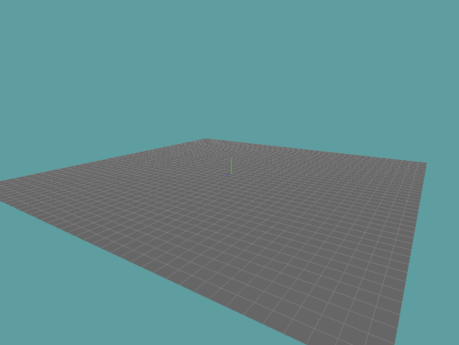
Thats all the changes we need to make to the grid. If you run one of the existing samples, and turn on RenderSolid on, your scene should look something like this:
Additional Geometry
You added the DrawCube function to every program that uses it. And you added the function DrawSphere to a calss called Circle. There is nothing wrong with this, its a solid approach. The circle code is better than the cube code for the sake that it is more portable.
However, neither solution is robust. Ideally you will have many different primitives to render, so we need a class that is a convenient holder for them. I would call this class either Primitives or Geometry. Go ahead and create this class in your project.
Add the code found at this gist to the class. Don't copy any of the existing code in your project, the gist is special in that it adds normal information (we will cover this later) for each primitive. The following static functions are exposed for you:
public static void Geometry.Cube();
public static void Geometry.Sphere(int nDiv = 2);
public static void Torus(float ringRadius = 0.2f, float tubeRadius = 0.8f, int numc = 6, int numt = 12)
As you can see, every argument has a default value, so you can call these functions without arguments. Cube and Sphere work like they always have. I've added some sensible defaults. Torus is new, what is a torus? It's essentially a doughnut. This is what a torus looks like:
When calling the function, the first argument is the radius of the ring, that is the radius of the actual tube which makes up the ring. The second argument is the radius of the tube. Imaging, that the ring is stretched around a tube, this is the radius we define here. So, first argument is how thick the geometry is, second argument is how large the hole in the center is.
The last two arguments are the number of segments to subdivide. The first one decides how many slices to give, the second one how many columns. Like with the sphere, the larger these numbers, the more detail the torus will have.
The test scene
With that we now have all the elements we are going to be using for our lighting test scene. For every lighting demo from here on, copy this scene, rename it and implement the light. For the scene, we're going to render a cube a spehere and a torus on top of a grid. And the camera is going to be slowly orbiting the scene to give us a 360 degree view of the lighting.
Let's build out the test scene, we're going to start with the initialize method:
namespace GameApplication {
    class LightingScene : Game{
        Grid grid = null;

        public override void Initialize() {
            grid = new Grid(true);
            GL.Enable(EnableCap.DepthTest);
            GL.Enable(EnableCap.CullFace);
            Resize(MainGameWindow.Window.Width, MainGameWindow.Window.Height);
        }
The first thing we do here is make a new solid grid object. We enable DepthTest, because we want the 3D objects to sort properly. We enable CullFace to save some performance by not rendering back-facing triangles. Finally, we call the Resize method, to set up our projection and viewprots. Let's take a look at said resize method next:
public override void Resize(int width, int height) {
    GL.Viewport(0, 0, width, height);
    float aspect = (float)width / height;

    GL.MatrixMode(MatrixMode.Projection);
    Matrix4 perspective = Matrix4.Perspective(60.0f, aspect, 0.01f, 1000.0f);
    GL.LoadMatrix(perspective.OpenGL);
    GL.MatrixMode(MatrixMode.Modelview);
}
This is a pretty standard resize method. Nothing to really talk about here. And finally lets take a look at how we are going to be rendering the scene:
 public override void Render() {
    Vector3 eyePos = new Vector3();
    eyePos.X = 0.0f;
    eyePos.Y = 5.0f;
    eyePos.Z = 10.0f;

    Matrix4 lookAt = Matrix4.LookAt(eyePos, new Vector3(0.0f, 0.0f, 0.0f), new Vector3(0.0f, 1.0f, 0.0f));
    GL.LoadMatrix(Matrix4.Transpose(lookAt).Matrix);

    grid.Render();

    GL.Color3(0f, 1f, 0f);
    GL.PushMatrix();
        GL.Translate(0.0f, 2.5f,-2f);
        Primitives.Torus();
    GL.PopMatrix();

    GL.Color3(1f, 0f, 0f);
    GL.PushMatrix();
        GL.Translate(2.5f, 1.0, -0.5f);
        Primitives.DrawSphere();
    GL.PopMatrix();

    GL.Color3(0f, 0f, 1f);
    GL.PushMatrix();
        GL.Translate(-1f, 0.5f, 0.5f);
        Primitives.Cube();
    GL.PopMatrix();

}
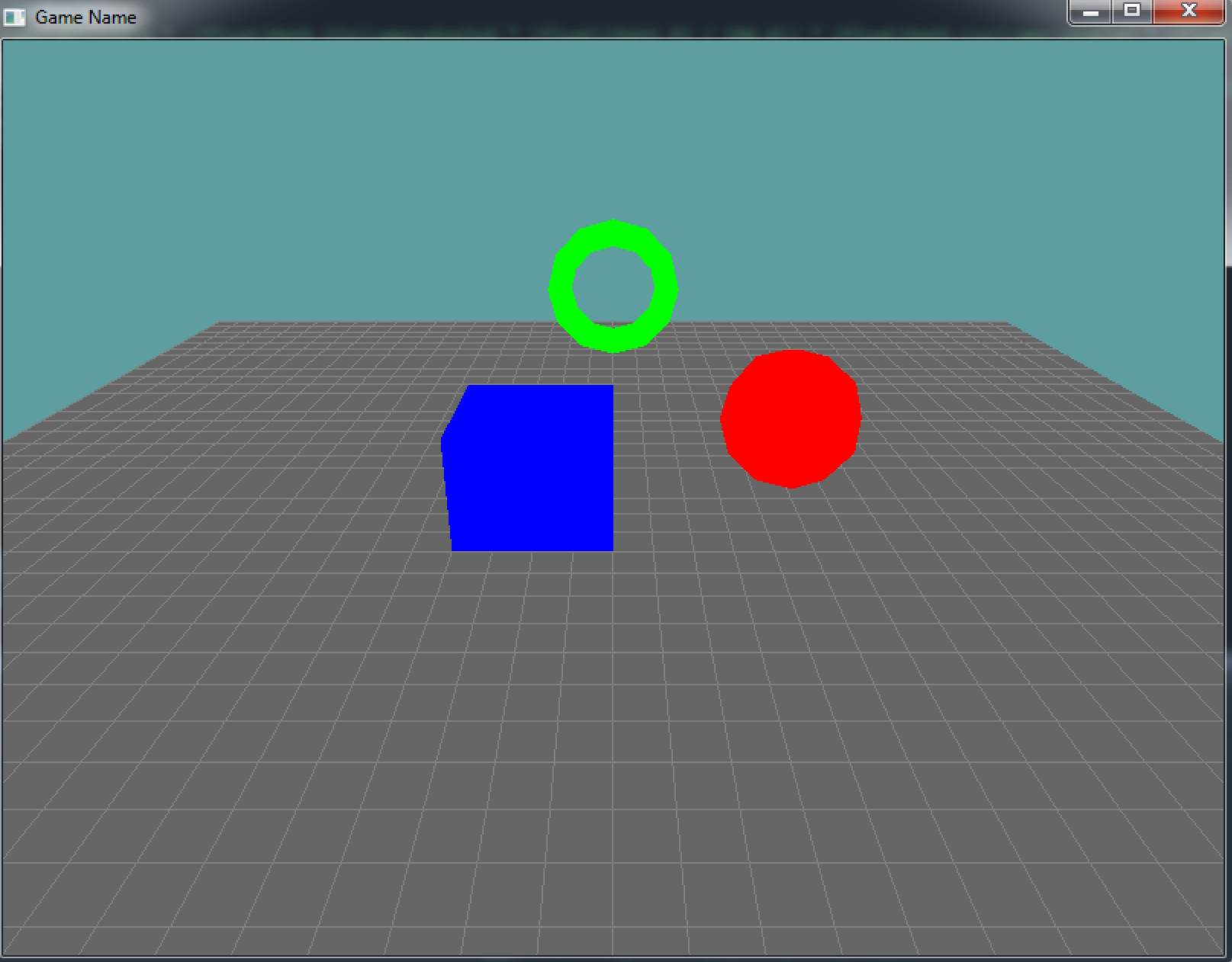
Again, nothing to brag about here. We set up a pretty standard view matrix, then render the grid, and then translate and render each primitive using their default values. The torus renders green, the sphere red and the cube blue. Your screen should look like this:
Now, let's rotate the camera! To orbit the camera around the scene, let's first add 3 variables to our program: angleX, angleY and distance:
namespace GameApplication {
    class LightingScene : Game{
        Grid grid = null;

        float cameraAngleX = 0.0f;
        float cameraAngleY = -25;
        float cameraDistance = 10.0f;

        public override void Initialize() {
            // ... rest of code unchanged
The cameras distance from what it's looking at isn't going to change, neither is the height at which the camera is looking from (cameraAngleY). But we're going to rotate the camera around the Y axis. For this, override the update method:
public override void Update(float dTime) {
    cameraAngleX += 30f * dTime;
}
Now that the angle is updating properly, lets modify the render code to respect these values. The following code should look familiar, it's standard rotation code that you've derived before.
public override void Render() {
    Vector3 eyePos = new Vector3();
    eyePos.X =  cameraDistance * -(float)Math.Sin(cameraAngleX * (float)(Math.PI / 180.0)) * (float)Math.Cos(cameraAngleY * (float)(Math.PI / 180.0));
    eyePos.Y =  cameraDistance * -(float)Math.Sin(cameraAngleY * (float)(Math.PI / 180.0));
    eyePos.Z = -cameraDistance * (float)Math.Cos(cameraAngleX * (float)(Math.PI / 180.0)) * (float)Math.Cos(cameraAngleY * (float)(Math.PI / 180.0));

    Matrix4 lookAt = Matrix4.LookAt(eyePos, new Vector3(0.0f, 0.0f, 0.0f), new Vector3(0.0f, 1.0f, 0.0f));
    // ... rest of code unchanged
The only thing new here is that we are multiplying the rotated angle by cameraDistnace. That's because our angle rotation returns between 0 and 1 (radians). If we multiply that by the distance of the camera, it makes the camera orbit around an imaginary sphere.
Try running the code, and confirm that the camera is rotating the scene. After this we are done, and read to actually start implementing some lights!